søndag 26. mai 2019

Lightweight, light duty spreader pole


Sometimes it seems like a curse and not a coincidence, that when sailing downwind, the apparent wind angle so often becomes around 150 degrees. Which will make the genoa ineffective on many sailboats, even when using a barber hauler. One good solution is to bear off course some degrees. When sailing on the Scandinavian coast however, the track is often dictated by terrain and the archipelago. Zigzagging downwind will also mean jibes, thus having to reset the sails often. Including preventers and barber haulers.

Previously I believed that the wide beam of a catamaran was enough to avoid using such a spreader pole that I saw some monohulls using. But I noted that the monohulls sometimes, with the help of a pole, could keep the genoa steady while I could not. That was a bit embarrassing, so I decided that I needed to try a pole. The drawback of the poles that I could observe on board the monohulls is that they are bulky, some are heavy, and they are a bit difficult to stow. I see many placed up in front of  the mast. That is not ideal for the airflow over the leading edge of the mainsail.

So what to do then? I decided I would make a lightweight prototype. For use as a spreader only, not a spinnaker pole. In my garage were a couple of windsurfer masts stored, and the longest of them was the basis for the project. I would have preferred a carbon pole, but did not want to buy one as I did not know if the project would be a success or a failure. But carbon is lighter and stronger.

The outer end contains a dyneema rope loop that can move a snapshackle outwards by pulling or winching the attached rope inwards. The best practical reason for the loop is that the shackle can be connected to the genoa more easily when the genoa is not stretched outwards.

There is a small simple Spinlock jammer that holds the rope tight and the shackle out towards the pole end. That specific jammer is not the best solution, it tends to lose the grip if the line is jerked frequently. At least it must be pressed hard down to grip the rope properly. The low friction ring is there so the line can be angled off to a winch.


The snapshackle is attached to a Dyneema loop in the genoa clew. The length of this loop, the snapshackle and the snapshackle attachment to the pole loop all together give some length capacity loss for the whole system. After the first trial season an extension of about 30 cm (one foot) was put in because I wanted some more capacity. This gave a total length of 4 meters (approx 12 feet).

The pole has worked very well for us, we use it a lot. I also put in an attachment point for it at the base of the inner forestay so that it can be used with a spinnaker too. That also works well, but as the wind shifts forward and the spinnaker approaches reaching, we have to be ready to remove it. The force on the pole rapidly increases and the pole can bend and break. That has actually happened. But that was at the point where the one foot extension was put in. I did that fiberglassing job too hastily, and the joint was too weak.

A long windsurfing mast is required for such a project. The tip will be quite thin and flexible. I did cut off some of it, also because the outer sheave needs a hole to be cut for it. In addition to that there is the hole for the sheave axle. If the mast section is too thin, this point will be weak. That said, that specific area must be reinforced anyway. Our catamaran does not have the widest of beams, 6.5m. For larger boats, this concept may be too weak. But as a spreader pole ours has worked with no sign of overload. (Actually, I believe the force required to push the genoa out and stabilize it is not huge. Most of us have sometimes been standing at the boat side, holding the sheet out manually with our arms for a short amount of time to keep the sail filled.) For larger catamarans I believe parts of more than one windsurfer mast glassed together can work. 


The spreader pole attaches to the mast by a shackle. A carbon fiber reinforcement ring at the connecting point for the end fitting can be seen.


This spreader pole stores easily attached to the stanchions by welcro tape. It even bends to follow the curve.


Some follow-up info regarding use with a spinnaker:


Sailing with the wind from behind, slightly in from starboard. Assymetrical spinnaker. Our simple setup is, I presume, like most other cruising multihulls for spinnakers. One guy and one sheet at each corner. We sometimes use only one guy and one sheet on the assymetrical, if the wind is expected to be stable.

Our mainsail is quite large, again like on most cruising catamarans, and will block a lot of wind for the spinnaker if the spinnaker is allowed to be pushed sideways downwind into wind shadow. This will happen if only using the beam of the boat for upwind support as is most commonly done. The spinnaker will be more unstable and less effective. Note the guy on the picture, pressed outwards and out of the main's wind shadow, instead of the opposite way. It can easily amount to 3-4 feet, and this can make a difference in sail efficiency. I think it really does help to get the spinnaker into free air and also at a better angle.

The non active sheet is used to pull the clew outwards and backwards. At fairly low wind speeds, the force on the spreader pole is not at all large as long as the wind is mainly from behind.


For spinnaker purposes, I found support for the spreader pole at the lower inner forestay bracket. Just drilled a hole for a shackle. And used some synthetic washers to stop any rattling. But I found that a stainless steel anti-chafe plate was nice to have in place to avoid ugly marks from the pole end fitting.

Again, this is a setup for fairly light conditions, not racing. But on the other hand, most people use spinnakers for light conditions.


onsdag 8. mai 2019

Deciding to test synthetic rigging


The recommended standing rigging change interval is as far as I have read 10 years. Many insurance companies will not insure a yacht with an older rig, or they ask a high premium. Our rig is approaching 20 years, but I have found no visible signs of wear. We crossed the Atlantic back and forth without worries with it when it was 15 years. However, experts point to the fact that you can not know the condition of swaged terminals, as they can not be inspected inside.

I believe the marine industry (and many others) keep maintenance and inspection intervals short to boost business. So, after careful consideration, inspection and googling, I usually have noe fear doubling the time for many products.

Well, for the rig we are almostat at the double point now. We plan to use the boat for many years to come, fate permitting. Therefore,  now would probably be a good time to change it.

As the multihull society is often rapidly catching up with new trends and products, I have of course read and heard about synthetic rigging. With its many advantages. And relatively little cruiser knowledge and experience. There are disadvantages too. But it sounds exciting.

After quite a bit of checking, I decided to give it a try. The cost savings would not be very large, due to several factors. Firstly, a riggers company would give a total price for a total job of installing a new stainless steel rig. I need a roller furling stainless steel forestay, so I had to go there anyway to have that done. Further, I do not have a solution for the diamonds in a synthetic version. I will have to wait, or have that also done by the riggers. And I wanted to buy a spare lenght of upper and lower shroud in case of miscalculating a splice. If all splices were successful, I would have cruising spares. They are light and fairly easy to stow.

The rope that is commonly used for synthetic rigging to date is SK75 dyneema, the prestretched and heat treated version is called Dux. There is information in the Colligo Marine website about rope and splicing.

The most difficult part for me was the calculation of the spliced shroud lengths. Most of the projects I have read about use lashings to tighten and adjust the shrouds, but for larger boats and heavy catamarans I read that turnbuckles are recommended. Turnbuckles are also fairly easy to adjust and you get an immediate impression of tensioning. But when using turnbuckles, the rope has to be spliced to a minimum and maximum lenght that is not within a large tolerance. Factors of uncertainty are how much the splices will shorten the rope, how much the splices then will restretch when tensioned, how will it be possible to prestretch properly, how much will the dyneema stretch when installed and tensioned?

Dux Dyneema is not unstretchable, it just stretches much less than other ropes. Like wire, which also stretches when pulled hard.


A technique that worked fairly well was to mark a point a distance (for example 2.5 meters for 15mm Dux) from the bitter end, when starting the first splice, that would be just outside the splice when the splice was finished.


Then use this calculation, after prestretch, to calculate where to cut the rope before starting the second splice.
For the prestretch I bought a 4 ton ratchet puller. A concern about such a puller is how easy is it to get 4 tons pulling power out of it? The 15mm Dux I pulled hard enough to break a cord or two due to friction in the reel (should have oiled it?). Still I have the feeling it was not quite enough.


I found some solid mooring points in a harbour in Oslo that I could use for the stretching.


After the prestretch of the first splice of all the lines, I knew where to cut them to achieve the desired length, using the exactly same splice. With the exception of one upper shroud, which ended up a bit longer than target, it seemed to work out well.


The splices themselves are not so complicated, I followed Colligo Marine's instructions, and did some test splices on smaller dyneema ropes. The fids required are maybe not the most common sizes, but it is easy to make DIY versions. I used some copper and steel scrap tubes, and fitted them with wooden tips as shown below.


For the 15mm rope, I found a heavy duty solution for the most demanding part of the splice:


You know you are working with strong rope when you are using a crowbar as a fid.


The rigging hardware is another area that needs a lot of planning. As thimbles are used in both ends of the ropes, not all products are useable. My previous system, ACMO, was not suitable. Nor were many others. The turnbuckles with forks and toggles would have to be wide enough to accept heavy duty thimbles. And also fit my chainplates. Upper mast connection to a thimble was also a challenge. The final solution was equipment from Blue Wave and some heavy duty shackles from Peterson.


The reason for using standard heavy duty thimbles is availability and price. I suppose it might be easier to find rigging parts using Colligo Marine terminators, designed to accept clevis pins. But I have not dug into that. Shipping and import taxes would rise the prices to unpleasant levels.


Colligo Marine tables and information were also used for the rope dimensions. As is common, the original rig wire specifications will be the reference for the stainless steel hardware. But for the ropes, a factor called creep will be dimesioning. Creep is something else than stretch, and when using the tables, one will find that the correct rope will have a larger breaking load than the original wire.


According to Murphy's Law, there will be surprises and setbacks when installing marine hardware. I knew that the clevis pins of the original rig were metric sizes. The new ones were imperial inches. Therefore, a slight widening of holes in the chainplate and mast fixing points were necessary. Easy match, I thought. But Marechal really had put some tough steel bushings in their mast. Dangling from my bosuns chair, sweating and cursing, I devastated my 19mm drill bit widening the holes from 18mm.


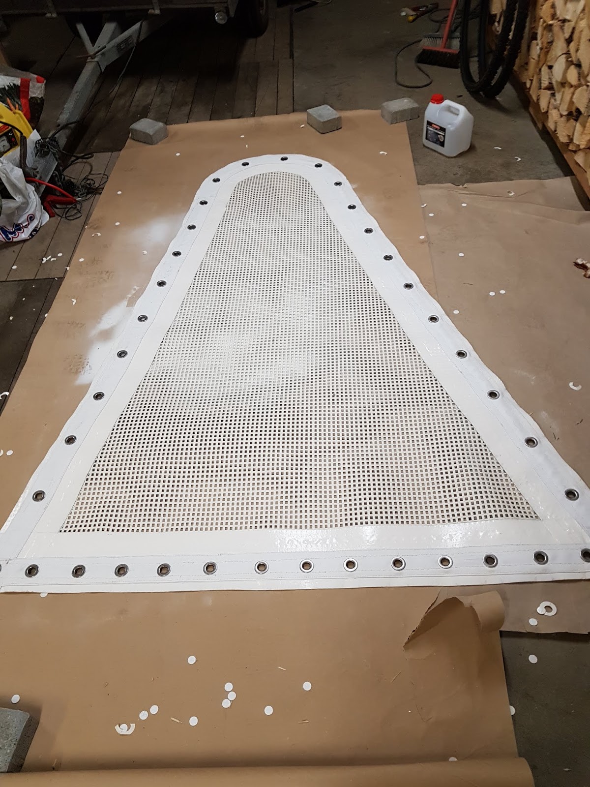
One detail that I have tried is to fit a simple 2 meter plastic tube, meant for electric cables, as lower end chafe protection. It must be installed before the second splice. Thus it can not be replaced. I do not know the UV Properties of such tubes, but they are cheap and worth the experiment. In addition there will be canvas chafe protection around the lower splices.


The ropes are now installed. Time will show how they will stand up to cruising demands. There are a few factors that are surrounded by some uncertainty for cruisers.


Obviously, as stainless steel has dominated totally for many decades, chafe will be on the list. According to the user experience I have read, the ropes will become a bit "furry" with time and UV influence. But they will be dimensioned structurally much stronger than stainless steel, and even some chafe will not weaken them substantially. I will try to avoid chafe the best I can.


Then there is hum. Some users report some humming from synthetic rigs, but it is not regarded as a problem or nuisance. We were quite scared when installing the upper shrouds. The mainsail dyneema halyard was used to support the mast while changing. It hummed like crazy. My wife looked at me in disbelief. Will it be like this? Fortunately not. There was no sound after installing the synthetic shrouds. But as we just recently have finished the rigging, we do not have experience from any length of time.

Report from june 2019: We do experience some more hum with the new rig. Obviously, as the wind picks up, there will be noise from all sailboat rigs. And from different parts of it. The wind hum now starts a bit earlier, and has a bit more bass to it than previously. But I have always had the feeling that there is more wind than there actually is when listening from the cabin, so the difference is not that great.  


What will happen in case of a lightening strike? Will the ropes burn? I have heard of no occurences, time will come up with user experience somewhere. Meanwhile, since we have a stainless steel forestay, I plan to install a copper cable from the seagull striker back to the chainplate. It will then hopefully work the same way as before. The chainplate is connected to the sea via the Dynaplate. Probably the same system on all Privilege yachts.


I do not know if insurance companies will object to synthetic rigging for long distance voyaging. Another issue may be the fact that you can probably not pop by any riggers shop and get a rig inspection and certificate? My impression is that not many places have this expertise.


On the side of positive bi-effects, weight savings is probably not enough to impress owners of fairly heavy Privilege's. The new rigging is approximately 20 kg lighter than the old system. For a catamaran, the fact that it is weight aloft is probably not as significant as on a monohull. The weight  difference would have been larger if using a lashing system instead of heavy turnbuckles. But as I have already tightened several times, I am happy with a system that makes adjusting fast and easy.


Update July 2019:
During installation of the rigging lines, it seemed that the longest upper shroud might be too long, depending on how much it would stretch and elongate in the spliced areas. This assumption proved to be right. I ran out of turnbuckle travel. Fortunately a shorter spare had been produced before leaving harbour for the summer, and it replaced the long one in mid july.

So now I have some new views on the prestretch procedures commonly distributed on internet blogs and discussions. My experience leads me to believe that the recommended short prestretch to the applicable value is not sufficient. It appears that the splices need to be stretched over some more time to settle permanently. The difference is significant. I tightened the turnbuckles almost as much as I could with a spanner. Only hours later I was easily able to tighten some more turns. The next day even more. A few days later more. A week later some more. Totally estimated 2-3 inches for my upper and longest shroud.

This would not be a problem with a lashing system dimensioned for some stretch. But again, lashings are not recommended for larger boats, and the frequent adjustments are cumbersome compared to turnbuckles.
If I had this knowledge when starting the project, I believe I would have had 2 options to get it right. The more unrealistic one would be to leave the lines in stretch for many days, reapplying tension successively. I do not know how I could have achieved this. Thus I would instead have made the splices 2-3 inches shorter, and used some rigging toggles to lengthen the shrouds  temporarily. Most probably the toggles could have been removed after some weeks of sailing. If not, given correct dimensioning, they could have stayed in place for a longer period.


Udate end of first season:

After the summer and a lot of sailing, the shrouds seem to have stabilized. But not before the lower shrouds are almost out of travel too. Still some tightening is possible, but I would have liked it to be much more. The tension will be released on all lines as soon as the boat is in the winter harbour. Thus the creep will be minimized.
Also, the plastic tubes intended as extra chafe protection were not a success. They are not fitted tightly, and as soon as there is vibration in the lines, the hum is amplified by the tubes. I have to be very careful not to damage the dyneema when cutting them away, thus this far I have only been able to remove the two largest. For the inner forestay I think I will need some other plastic chafe protection, as the genoa and its sheets are often flying over it at high speed and pressure when we tack. But I will try to use the old fashion split tubes that cling more to the stay. There is another problem with that solution however, a stormsail with metal hanks will probably chew up the plastic quickly. So a softer solution is needed. Dyneema softshackles is a possibility, but hanking the sail on in bad weather will be cumbersome. Then again, it is recommended to have the stormsail ready and hanked on when on longer passages.


tirsdag 30. april 2019

DIY sailmaker


We have ruptured more than one spinnaker while learning to sail and find the limits of our boat.  Expensive learning, fortunately we buy used spinnakers. Which I guess is easier to destroy....

A sideband is not so difficult to replace, but when one or more corners are totally torn off, we usually give up. However, after bringing a rupured spinnaker home and looking at it, Tove Irene wanted to try a repair. As we had other wreckage available, spare fabric could be found.

Wannabe sailmaking is of course not a guaranteed success. Replacing all the destroyed panels fully would be too complicated for such an uncertain project, so small panels on both sides across the tear and reinforced seams along the vertical panel lines is our solution.

Now at least we have a spare spinnaker. Time will show how it will perform.


This clew was completely torn off.


The top was also in bad shape.


Panels. Will they be strong enough?


Home based sailmaker.


fredag 12. april 2019

Fenderboards


It takes time to gain experience as a sailor. More time for some than others, maybe. I wondered for many years what was the purpose of the planks attached to the rail wire of some yachts. Never bothered to ask. Maybe I should have, it might have been beneficial to have such ones coming into a crowded harbour for the night.

Tying up to pilings for the night is not so common or popular in Scandinavia. You do not see that many yachts carrying fenderboards. And in the the majority of harbours you do not need them. But in some you can find unused possibilities in the high season if able to tie up to pilings, fully or partially.

Inspired by the Practical Sailor July 2018 issue, I this spring went on and bought a length of 1 1/2 x 6 inch pine plank. Maybe I would have chosen 2 x 8 if sailing out in the big world, but that size is considerably heavier.

I have seen some simpler versions, but I like the PS one. I want the fender loops, I believe they will prevent the fenders to act as a roller bearing between the hull and the board. The common solution is 2 fenders, but holes for using 3 fenders were drilled. Then again, probably no fender loop will be strictly necessary for the middle fender.

Also the recommended 5 feet length was accepted. Seems to be OK for storing inside or along the rail. And maybe still long enough to double as gangway in some instances, if joined with the use of a couple of  long transverse bolts.

To simplify storage, I want as few as possible permanent lines attached. Therefore the plan is to use dyneema loops as attachment points for suspension lines and for the horizontal fixing lines.

Finally, a layer of wood preservation oil will be added to prevent water soaking into the boards.  That would only make them heavier.


Recessed holes on the outside to prevent line chafe.


Also a recess at each end for the protection of the planned dyneema loop


Planned dyneema loop fitted.


fredag 15. februar 2019

Trampoline net mounting technique


Ref below, we mounted the starboard net today. I have been wondering for a while how to get the nets correctly positioned and tightened. We do not want to use many short lenghts of line, even if this makes the job easier. It will result in many ugly rope ends and knots. On the other hand long lenghts are cumbersome and make it more difficult to tighten the nets up. The working position is also uncomfortable at the edges of the hull with no guardwires and 3 degrees centigrade water below.

So we pre-mounted with plastic strips. This way we were able get the right positioning  and stretch before tying the lines. In relative comfort and safety.


onsdag 16. januar 2019

Trampoline net repair


The boat has been operative and in quite a lot of use for many years now. She is a year 2000 model. Some equipment is showing signs of wear. The trampoline nets were in a condition after last summer that required something to be done. Preferably new nets. But the original ones are of a high quality type, and expensive. A Privilege uses two nets. Also, they would have to be ordered from abroad, meaning that additional shipping and import fees would apply.

So a repair had to be considered. Several of the grommets were corroded to disintegration, all were showing some sign of corrosion. Around many of the grommets the fabric was stretched and torn so much that I feared new eyelets would not grip properly.


Some kind of reinforcement was necessary. And some high quality grommets. The original grommets were brass with some kind of coating, probably chrome. I wanted large stainless steel ones.

And again, as Norway is a small country with a limited marked for everything that is not quite common merchandise, I had to look abroad. As often before, the US had the solutions. For Norwegians, at a price. The largest grommets I found available in stainless steel were slightly more than an inch in diameter, US #5, from Fasnet. They were willing to ship to Norway, which is not always the case.
I wanted to use strips of heavy duty fabric along the rows of grommets to reinforce that area. The most promising I found was heavy duty vinyl coated polyester from Tarpsnow. Had to go through a reship service to get it home.

With the parts and materials available, a repair could be attempted. Luckily I discovered that the nets could be used with the reverse side up, if changing sides. They look fresher on the less exposed underside. 

I cut the strips, and a sailmaker sewed them on. The grommets came on nicely, and the end result looked good and promising. I hope the nets will now last for many more years.


onsdag 26. desember 2018

More macerator trouble experience.


Changing gaskets in April this year did not fix the leak in the macerator. I should have checked more on Youtube about macerator overhaul. But at last I bagan suspecting another reason, and in particular the motor shaft seal ring. (11)


This was the only probable reason beside the gaskets. And removing the seal ring revealed that it was stiff and worn. Also, the inside tightening spring was rusty and probably inoperative.


When installing the new ring, I filled the spring with grease, hoping that it will prevent rust for a longer period. The next summer will show if the leak is stopped.

And testing in may 2019 it looks very promising. No leaks any more.


tirsdag 25. desember 2018


Checking the exhaust bend....at last.


I really try to take care of my 2 engines, honest. The oil is changed every year, dieselfilters quite often too, cooling fluid as well. The intake and exhaust valves have been adjusted a couple of times, cooling heat exchangers cleaned, transmission oil checked to be OK now and then. The two MD 2030's do not work a lot, they are mainly used in and out of harbours and anchorages. And they have not let us down, the only trouble being an occasional loose contact on the starter relay. Which can cause a bit of panic in the wrong moment, but it has not been critical.

But now I understand I have missed something important. Reading in social media about cooling problems, attention was directed towards the exhaust bends. Our engines have not overheated, and cooling seawater always came through. But I have never previously  checked the exhaust bends for clogging. It appeared to me that because the engines run mainly on low speed for maneuvering, exhaust deposits might form more easily in our engines.

So this autumn it was time to check this. And the suspicion was confirmed. The exhaust bends were quite badly clogged. Even though water came through, further clogging would have caused overheat. And I believe the power will be restricted when the engines can not breathe well.
So the exhaust bends were cleaned. But maybe some other issue is lurking around the corner, me happily ignorant about it....?


lørdag 16. juni 2018

A new Spade incident...


We sailed into the Limfjord (Jutland, Denmark) from the east, and would have to go through two lifting bridges before reaching the planned marina. A nice southeasterly wind brought us in to Aalborg at the right time for an hourly opening. But alas, a boat race was going on, and all traffic was stopped for more than an hour to come. So we had to find a place to stop and wait, and chose to drop the Spade in the vicinity of another sailboat which was also waiting. In the process, i came quite close to shallow water, so I did not want to back the anchor in as we otherwise always do. We were on watch to keep an eye of things anyway.

After a short while we recognized the unpleasant condition of anchoring in opposite current and wind. The current lined us up with the stern towards the wind, and the wind pushed us over the anchorchain. If the wind is strong enough and when anchored in shallow waters, this may easily keep scratching the anchor chain into the hull and keels. So we decided to try to find a place to tie up instead. As the Spade came up, it was like a mirror of what happened to us in Des Haies  in the Caribbean in 2015 (see previous post under this tab).


This is scary. It is the third time the Spade comes up with the chain wrapped around it, and in a condition that prevents it to reset. The two first times, there had been definite boat position shifts and drifting. But the anchor had been backed in.

It must be recognized that this last time is a bit special. The anchoring technique was really poor, I did not slowly drift back while the anchor chain came out (being cautious and preoccupied with assessing shallow water behind). Thus much of the chain was probably placed very close to the Spade. In addition I did not back it in. Had it not been for the previous incidents, I would not have reacted much to what I saw. Now however, I see a big problem with the two side "wings" (vinge) of the Spade. Due to these, the anchor chain will not slide free if the anchor is pulled or lifted. The Spade is effectively rendered useless, and the boat is free to drift. 

It seems like some second  and third and even more thoughts have to be made before anchoring with this anchor in shifting winds or currents. I believe the seabed has to be soft enough to bury the anchor so deep that the chain cannot creep under the "wings". This excludes rocky or hard clay seabed, maybe even seagrass, which normally might be OK under fairweather conditions. Unfortunately, in many parts of the world you can not see the bottom or your anchor through the water.

Spade anchors have shown good properties during tests regarding directional resetting. But this is with one strong directional reversal pull.

So is it time to change the anchor? It seems to me that Spade and Rocna are the overall winners of most anchor tests. We cannot use a Rocna due to the roll bar. And it seems the Rocna also has such wings, but maybe smaller. Maybe the Vulcan is a good alternative.

At least it is time to be even more conscious about seabed and anchor penetration when anchoring in shifting wind and current, even under light conditions.

torsdag 7. juni 2018

Calorifier installed


The installation is finished, Almost according to plans. The power supply cables had to be changed after the initial installation. I used a cable dimension approximtely equal to the short one supplied on the calorifier. Too thin. The power supply cable from the circuit breaker box is around 3 meters long, and it got warm (not hot) when power was switched on. This of course means an energy loss, and new cables, believed to be around 10mm2 was installed. That was much better.


And speaking about energy, an effort is made to save every Joule possible. The picture shows the extra insulation laid around metal parts (tubing connections) that leak heat from the water in the tank.

From quite cold water it took more than one and a half hour to heat up the tank. Less now that the summer has arrived. Calculating from a 25A consumption and 1 1/2 hrs, this means around 40Ah spent. The first testing period has been very sunny and also given some wind, thus the surplus energy I mentioned in the previous post has been present. And the heater has been used every day. It would have been nice to have Lithium batteries, then I could have "borrowed" more power on overcast days without being concerned about recharging lead batteries. 

But the amount of well heated water is quite limited. All such tanks take in cold water for pressure in the bottom, and as the tank is small, it seems to mix in fairly rapidly. Still, it is nice to have some hot tap water for rinsing the greasy frying pans and pots. Warmed by surplus energy otherwise not available for use.


lørdag 12. mai 2018


Calorifier....?

What is that? As a Norwegian I had never heard the word before starting to look for a 12 Volt water heater.

Luckily, nowadays boat equipment steadily improves with time. Comfort levels rise, and possibilities increase. On the Lucky Strike we now have a fairly comfortable amount of solar panels. Enough to keep the batteries charged most of the time when not using shore power (which is almost all the time). In addition there is a wind generator and of course the engine generators. Even though the batteries are old fashioned AGM that requires much energy to enter top charged condition, on sunny and/or windy days we actually have an energy surplus. But this surplus ends up blocked by the solar regulator or being led into the wind generator dump load. That means it is useless.

We would like our boat to be well equipped for cruising, and this means being independant of shore power and also use the engines as little as possible for battery charging and hot water production.
Our concept has a weakness from a comfort point of view regarding hot water. Without shore power, the only hot tap water source is the port engine coolant fluid. The hot water tank is 40 liters, so the engine use when entering a harbour or when anchoring is by no means enough to heat it. In addition, we usually motor on one engine ony, which means that no hot water is produced when it is the starboard engine's turn to contribute. It would be nice to have a more available source of hot water, be it only for dishwashing, personal hygiene or a short shower.

It will have to work on 12V. And thus be quite limited in volume. And the immersion heater in it must not load the batteries too heavily, better to use a bit more time with less power.


Is this the solution?


It draws around 25A. I do not know how long it takes to heat up to acceptable temperature. But I presume that it will vary a lot with the starting temperature.  Big advantage is that it will be usable with the starboard engine producing electricity.

A possible setup will be to use a selector valve between the 2 tanks hot water feed line to the galley and owners suite.

So I have ordered one. Hope to be able to install it this summer. It would be very exciting to see how it turns out.


tirsdag 24. april 2018

Macerator through bolt failure again.


Found the macerator leaking this spring. Once again, brass through bolts had broken, 2 of 4 this time.
In the other macerator I have fitted stainless steel replacements, simply made out of treaded bars.

Maybe the frost has broken the brass. But I have of course run the system with anti-freeze in the autumn. The only question then is if it was enough. The steel reinforced one did not break.

So I am still a firm believer that the brass used by the manufacturers is too weak. Causing unnecessary failures. I also think many boatowners do not want to mess with macerators. Which then boosts the sale.

I did fit stainless steel into the failed macerator. Time will show how it works.


søndag 8. april 2018


How you could (but probably should not) make a
bimini hardtop.


I will make my blog post in english again, because it seems there are many foreign readers.  

Most modern cruising catamarans have some kind of bimini installed. On a catamaran this is a great and cost effective way to increase living space on board, as the cockpit area is often spaceous. The main manufacturers realized this many years ago, and now integrate hard biminis on their cruising models.

The composite hard bimini has many advantages. It is very durable, strong and completely water proof. It is fairly easy to attach many solar panels and also water collection systems to it. On the underside lamps and gear storage equipment can easily be mounted almost anywhere. A composite hardtop bimini can be left in place permanently with minimal effects from weather. If built strong enough, the hard bimini can be walked upon, rendering easier and more safe access to the full lenght of the boom. In addition, by building a curved (convex) surface, water pools that can easily form on large canvas biminis will be avoided.

The downside is added weight and cost/labour. For some, the loss of the canvas removal option for storm preparation might also be a barrier. 


We (my poor wife is involved in all kinds of wild projects) have changed the original bimini cloth only once in 14 years. But the advantages of a hard structure are tempting, so when a long distance trip of several years was planned, an effort to build a hardtop was initiated in the winter of 2013/2014.

The Norwegian winter is not ideal for home building of large composite structures. Especially in the area north of Oslo. Temperatures are mostly below freezing, and a spaceous heatable garage area will be needed. Luckily we have a quite large garage, and part of it was sectioned off with tarpaulin walls to minimize the heating requirement.

The first challenge was to dismount the bimini stainless steel frame and trailer it home. It passed through the marina pontoon gate only using advanced twisting motion and hardly an inch clearance. On our tiny car trailer it looked a bit oversize.


The somewhat ambitious plan was to build a plug on top of the frame and then lay up a fiberglass mould on top of that. So why did we want the same size and shape as the old bimini? For one thing, the old stainless steel frame or main parts of it could be used. Fitting would be easier that way. And I actually did not want to build the hardtop overly strong due to weight considerations. It would be fine only to be able to walk reinforced areas along the boom. Kind of the same concept as a canvas bimini. Many would have made the hardtop a bit larger than the original to have better sun protection. Unfortunately it is very probable that our time on the catamaran will be longer in northern latitudes where we need the sun, than in the tropics. We also have a winterization problem. I like to have the main parts of the boat under a tarpaulin which is laid over the boom, and the wider the hardtop, the more exposed it would be to snow loads. The final argument for my choice is esthetic. I think the flatter shapes looks better and works better in the warm climates.


 Starting building the plug.

A plug can be made of sheets of fiberboard. If you do it the right way. The right way requires much time and effort. For us neither was abundantly available. We had a lot of other projects going because of the planned departure late in May 2014. Another consideration was that this was a one-off project, so the mould would be used one single time and not for further production. Being pressed on time, it seemed sensible not to put more effort into it than absolutely necessary.


The plug skin almost finished. The fiberboard must be thick enough to compensate for the layers that will later be built up in the mould. This to ensure that the hardtop will fit on top and outside the stainless steel  frame.


Nevertheless it was quite some work to shape the plug. And make it ready for the special tooling gelcoat. Reading about such gelcoat, one is warned that the plug surface must be painted with many layers of polyurethane paint to avoid it adhering to the plug. 

Makers of such instructions usually exaggerate to be on the safe side, don't they? And do they know how hard polyurethane gets and how much work it is to sand down the wave pattern from the paint roller? And furthermore, how easy it is to sand through to the fiber board around edges? Probably not....

To avoid that the mould would stick to the plug, many layers of Carnuba wax was put on the plug.


Then came a hard days work . Laying out the mould gelcoat. Laying up layers of fiberglass chopped strand mat. Cutting and shaping 20 mm Bonocell foam (for stiffness), and laying up the top layer of chopped strand mat.


Resulting in this top view of the mould at the end of the day.


The  inside of the mould did not turn out satisfactorily. More like a disaster, actually. The fiber board stuck to the gelcoat along edges, and the inside of the mould was more or less a mess because of bonding to the plug. But it generally had the correct shape, so giving up was not an option. 


By filling and sanding the mould was smoothened, and then painted with spray paint. Epoxy is much more forgiving than gelcoat when it comes to not dissolving the underlying surface, right?


I mentioned added weight as one of the drawbacks of adding a hardtop bimini. I have wanted to limit that drawback as much as possible. And have tried to find ways to save some weight. We have all read about the fantastic strength and weight savings of vacuum bagging techniques. So in that lies a possibility. Youtube videos explain how easy this is, and information sources tell you the opportunity must not be missed if you want to save weight and gain strength.

Unfortunately bagging equipment is not so readily available for retail in Norway. I envy the americans, their domestic market is so huge that just about anything is easily purchased, and at a reasonable price. 
Turning to that market is a solution, even though our VAT and the shipping cost increase prices significantly.
New words now came into my vocabulary. Peel Ply, Vacuum Bag, Bagging Release Film, Bleeder Breather Cloth, Tacky Tape Vacuum Bag Seal, Nylon Vacuum Bag Bagging Infusion Film, Resin Trap, etc.  
A vacuum pump is also needed. These are in no way meant for a single occasion use, they are quite expensive. But again, internet is the saviour. I found information that a refrigerator compressor unit can be used. Easily taken from an electric appliance dump.


The process of acquiring all the necessary gear took some months, But at last we were ready for a very hard and stressing day. All the fiber glass weave had been pre-cut to shape, likewise the 10mm Divinycell foam and the vacuum bagging equipment. The vacuum pump was tested to be working and ready. 

The epoxy resin hardener was specified as slow, still we knew that we had to work fast. But laying out epoxy, top and bottom layers of weave and the foam on such a large area took a lot of time. In addition the rim and hatch area had to be set up. But worst of all, the hardener was not very slow. Already after the first 2 layers of weave, I felt failure creeping in over us. The resin started to get viscous. Even frantic work could not save us. When all the layers were in and the vacuum bag sealed, it was already too late. It did not help us a lot that the homemade vacuum pump was way too weak to do its job, but it could not have saved the day anyway.


As suspected, after having a hard time getting the bimini out of the mould (release problems again), it was clear that it could not be used. It delaminated easily because of insufficient bond between the layers. Departure date for the Caribbean  was coming close, so there would be no hardtop bimini for that voyage.


The product had to be cut in pieces and taken to the dump.


Lesson learned is that if vacuum bagging a project of this size, infusion technique should be used. In addition I suspect that the epoxy resin and hardener may have been old, and therefore curing too fast. When using leftovers of the same stuff now, it starts curing really fast.


None of us thought that we would ever want to try such a project again, but the mould was anyway hoisted up under the garage roof for storage before departure.


The canvas bimini did its job fine during the two year cruise. But the weather and use wore on it. And after returning home the thoughts of a hardtop again surfaced when repairs were necessary. In the autumn of 2017 the mould was taken down from the roof and rigged on the garage floor. It was going to be difficult to use it, as the gelcoat inside was damaged after the first use. So I expected to have to repair the final product extensively. But a new mould was not an option, way too much work.

Like the first project, this would be epoxy and divinycell based. I have learned that the common gelcoat topping can not be used  in such projects, it is polyester based and does not match well with epoxy. Paint is thus the usual top coat. And in that case some surface work will be needed anyway.

Divinycell comes in sheets, precut into small squares and uncut sheets. I like the precut. The 3 x 3 cm squares are glued on one side to a thin glass fiber weave with a small gap between each square. Thus the sheet takes the shape of the underlying mould much more easily, and does not have to be weighted down so carefully. Another advantage is that resin fills the gaps in the sandwich construction, so no specific holes or areas to bond the upper and bottom layer to prevent layer skidding are necessary. On the other hand this concept may require more resin and be a bit heavier.

When buying glass fiber weave this time, I also learned of twill weave. Again, this type of weave is much softer and will shape around spheres and corners much better than ordinary weave. The only small disadvantage is that after cutting out a shape, it must be handled carefully because it easily twists out of shape.

Epoxy resin is more expensive than polyester. My reason for using epoxy was again weight considerations. Epoxy/fiberglass is a very strong mix, stronger than building with polyester or vinylester.  I do not think it is lighter per se, but one can use less materials for the same strenght, thus there is a weight saving potential.

Before the first attempt I had made a couple of test sheets, and found 2 layers of 300 grams glass fiber weave each side of 10mm divinycell very promising. I did use the same in the second attempt.


Here is the hardtop plan.

Without the stress of the vacuum bagging setup, the casting of the hardtop was a bit easier. One should however remember that if too much time elapses between layers, the surface must be rinsed before continuing. This is because of the so called Amine Blush, the next layer might have problems sticking to the previous.


Laying epoxy, fiberglass and divinycell in the mould.


With my substandard mould inner surface layer, I knew I had to expect problems with getting the product out of the mould. So I did follow the advice of attaching a tube to the underside before casting. With a piece of tape on top to prevent resin escaping that way. Good move, without it the job of getting the hardtop out would have been a nightmare. Now I could pump in pressurized air from the bottom. Which made the difference.

And no, the product surface was not perfect. It was repair time in sevaral ways. In some smaller areas I had to re-bond the upper surface due to too little resin used. ("weight saving" is not always a success). And the whole surface did of course have to be sanded and smoothed before painting.


Polyurethane paint was used as the top layer. Using a paint roller will not give the same finish as sparaying, but spray painting polyurethane in the garage was not worth the trouble for me.

Our original plan included a sliding hatch, but when I discovered that the front and back of the hatch opening inclined at very different angles, I realized that it would be complicated. So the solution was a folding hatch from canvas and composite planks. Luckily my wife is now quite experienced in sewing canvas.

When the hardtop was mounted, it became clear that it was quite stiff and strong, at least when using it atop the stainless steel frame.  (Also, below the gangways the thickness was doubled). I had beforehand cut away some obviously superfluous sections of the frame, and plan to cut more. But first we would like to observe how the hardtop works the next season and winter.

In our home climate canvas sidewalls is a necessity. For mounting these. we chose  to use a band of canvas around the edge, supporting YK 10 zippers. The canvas was caulked onto the inside, We will find out if it has to be supported by screws.

The original dream for the project was that it would be all composite and that the stainless steel frame could be taken away. It weighs 40 kg. I believe it is absolutely possible, but it would require  a lot more work and time. Having the boat an hour drive from home would also complicate such a solution a lot. Not to speak of the long season of temperatures when it is too cold for outdoor composite work. In the summer we want to cruise, not work.
So the hardtop now adds approximately 33 kg (73 lbs) of weight, hatch included. ( It is a bit heavier, I deduct the old canvas and the cutaway stainless steel parts).

But as everyone who has added one, we think it will be worth it all.


.


The great day of mounting it.


søndag 17. juli 2016


God erfaring med nedlasting av GRIB via Iridium denne gang.


På vei til Karibien strevde jeg mye med Mailasail sitt opplegg. Hadde vanskeligheter med å få koblet opp til nettet og serveren deres, telefonen koblet av for tidlig når Redbox ikke registrerte aktivitet.
Ekstra dyrt ble det også, de tok betalt for tilgangen til mailsystemet sitt.

Så på tilbakeveien ble det å prøve noe annet. Hadde hørt at Iridium Axcess Point virket bra for andre. Dermed ble det anskaffet en slik. Selv om denne er relativt gammel teknologi, og selv om Iridium selv offisielt ikke støtter denne lenger. De vil heller selge GO, som er mye dyrere.

Vi bruker eksakt det samme Iridium basisutstyret som før.

Nå skal det sies at det er litt konfigurering av det nye opplegget også, og jeg kontaktet Iridium for å få det til fungere sammen med appen Iridium Mail and Web. Men når det først var i gang, funket det veldig bra synes jeg. Vi lastet ned ganske så mange store GRIBfiler, og selv om det ble noen få feiloppkoblinger og nedlastingsavbrudd (sikkert pga dårlig satellittsignal), så var det aldri tvil om at vi kom til å få de væropplysningene vi bestilte.

Dette er jo også takket være Saildocs, som har en server som svarer lynraskt på forespørslene og har et stort utvalg av nedlastbar informasjon. Tjenestene er gratis fra deres side (man har jo utgifter til Iridium internett, selvfølgelig).

Jeg synes kommunikasjonen gikk ganske effektivt. Appen bruker visstnok kompresjonsteknikk. Ut-mailen gikk totalt gjerne på under et minutt. Til Azorene tok vi ned store GRIBfiler, rundt 25kb. De kostet vel rundt 3 minutter.


Skjematisk tegning av satellittopplegget for hjemturen.


I appen Iridium Mail and Web er det en loggfunksjon som viser hva som skjer under oppkobling, opp/nedlasting og nedkobling. (Nedkobling etter mottak av mail virket ikke, måtte slå av manuelt)

tirsdag 17. mai 2016


Forskjellige GRIB-lesere til forskjellige formål.


Et av mine GRIB favorittprogrammer ved siden av zyGrib er qtVlm. zyGrib er et enklere program å få til å fungere synes jeg, med muligheter til enklere visning av flere forskjellige typer værdata.

Og qtVlm kan virke noe mer komplisert å komme i gang med og forstå. En god del funksjoner bruker jeg ikke, andre som jeg kunne tenke meg å bruke får jeg ikke til. Det er ikke så farlig, det som jeg synes er så bra med qtVlm er den seiltaktiske oversikten visningen gir når man er ute på sjøen. 

Vindpilene sitter så tett som hagl. Kombinert med båtens GPS-posisjon gir dette raskt og nøyaktig overblikk over varslet vindvinkel og styrke. (De fleste som reiser på båttur med PC har vel med seg en kompatibel GPS). Ved å sette inn distansemerker langs ruta via «Marks» funksjonen, får man enda lettere se vinden som venter i diverse posisjoner der fremme. Og kan legge ruta fordelaktig i forhold til prognosene. Så får man bare huske at prognoser av og til ikke stemmer. (Men hva er alternativet?)


Programmet interpolerer til detalj også de GRIB filer som har lavere tidsnøyaktighet enn den man velger å se. Akkurat det kan jo også gi uventete unøyaktigheter, men nåtidens ferske GRIB filer er som regel så bra at det ikke er et problem. Og min egen interpolering blir veldig omtrentlig eller uforholdsmessig tidkrevende uten bedre resultat.


Lucky Strike korrigerer gradvis sørover på vei mot Bermuda etter å ha gått nord for høytrykk og vindstille. Dagsetapper ligger merket langs direkteruta.


Som nevnt synes jeg qtVlm kan være litt komplisert å få i gang. Hos meg er det heller ikke helt stabilt, krasjer av og til. Ikke så farlig, bare å starte igjen. Hjemmesidene er videre nokså rotete, men har man holdt på litt med PC så finner man ut av det. Husk å merke av for nedlasting av kart for å få bra funksjonalitet. GPS må konfigureres til egen com port. Programmet har egen nedlastingsfunksjon for GRIB. Dersom man liker å hente GRIB på andre måter, slik som jeg, må man hente dem andre steder på PC via «Open Grib». Ellers må man prøve seg frem for å få det til som man ønsker å ha det.